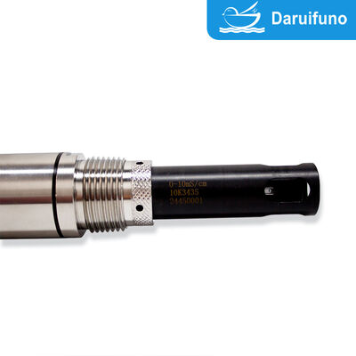
Product Overview
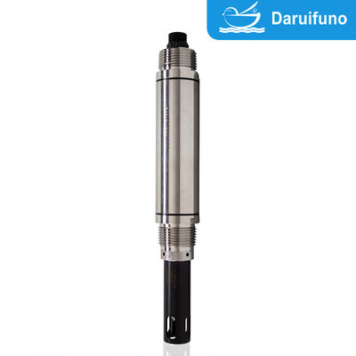
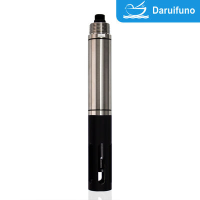
The DEC890 conductivity electrode is the installation-flexible version of the DEC890 digital conductivity family. Its defining feature is mechanical: the stainless steel 316 body is machined with a 1-inch NPT thread at both ends, which means the same sensor can be screwed into a pipeline tee, bolted to a top flange adapter, mounted on a side wall bracket, suspended as a submersible probe, or fitted into a dedicated flow-through housing. One spare part therefore covers every mounting position in a plant, which simplifies procurement and reduces the number of variants a maintenance team has to keep in stock.
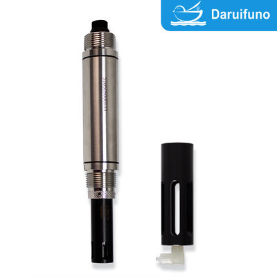
Measurement uses the graphite two-electrode principle. Two parallel graphite plates are placed in the water, a driving voltage is applied across them, and the conductivity is calculated from the current flowing between the plates. Graphite is chosen because it substantially reduces polarization — the electrochemical effect that causes metallic electrodes to drift in continuous service — so the reading remains stable across long immersion periods and in water with a moderate fouling tendency. The measuring unit is a replaceable structure, so a worn cell can be exchanged without replacing the body, cable, or electronics.
The body is 37 mm in diameter and approximately 261 mm long, sealed to IP68 and rated for 0~1 Bar working pressure and 0~50°C water temperature. Power and RS485 communication are electrically isolated, and the sensor runs on a DC 9~36V supply while consuming only about 0.2 W.
Installation Flexibility
Mounting position is the most common reason a conductivity sensor underperforms. A probe fitted in a dead leg reads stale water; a probe too close to a pump suction sees bubbles; a probe in a horizontal pipe top collects gas pockets. The DEC890 conductivity electrode is designed to remove that constraint: with 1-inch NPT threads at both ends and a slim 37 mm, 261 mm long 316 stainless steel body, the same sensor can be installed in whichever orientation the process actually allows, and re-used elsewhere when the plant is modified.
Five installation methods are supported:
- Side wall installation. The sensor is screwed through a tank wall fitting with the measuring end fully immersed and clear of sludge.
- Top flange mounting. The probe is suspended from a flange adapter for open tanks, channels, and basins, with the measuring end kept well below the minimum water level.
- Pipeline installation. The sensor sits in a tee at a low point of the run, where flow is steady and bubbles do not accumulate.
- Submerged installation. The front section faces the direction of flow and is pushed deep into the moving water body.
- Flow-through installation. The probe is fitted to a dedicated bypass chamber so that it can be isolated and removed for calibration without stopping the process.
Measurement Performance
Measurement covers four factory ranges — 0~20 uS/cm, 20~200 uS/cm, 200~2000 uS/cm, and 2~10 mS/cm — with 0.01 uS/cm, 0.1 uS/cm, or 1 uS/cm resolution and an accuracy of ±1% of the selected range. Temperature is measured from 0.0 to 50.0°C with 0.1°C resolution and can be compensated automatically or manually over 0~50°C, so seasonal temperature swings do not distort the conductivity trend used for control decisions.
Communication is RS485 MODBUS-RTU: address 17, 9600 bps, no parity, one stop bit by default, with values returned as 4-byte floating point data in little-endian byte-swapped order. Offset, factor, two-point, and up-to-five-point calibration are all supported, and the calibration can be reset to factory values through a single register write. Because supply and communication are isolated, the electrode can share a long RS485 bus with other digital sensors without ground-loop problems.
Typical duty includes sewage treatment plants, water plants and water stations, surface water and environmental water treatment, metallurgy and electronics, mining, paper industry, and semiconductor manufacturing — exactly the environments where sensor position, fouling, and cable routing decide whether a conductivity reading is trustworthy. A standard 10-meter shielded cable with M16 connector is supplied, and longer lengths can be specified for deep tanks and remote channels.
Technical Parameters
| Measuring Principle | Graphite two-electrode measurement principle (polarization-resistant graphite plates) |
|---|
| Measuring Range | 0~20 uS/cm / 20~200 uS/cm / 200~2000 uS/cm / 2~10 mS/cm (switchable models) |
|---|
| Resolution | 0.01 uS/cm, 0.1 uS/cm, 1 uS/cm |
|---|
| Accuracy | ±1% of the measuring range |
|---|
| Temperature Range | 0.0~50.0°C |
|---|
| Temperature Compensation | 0~50°C, automatic or manual compensation |
|---|
| Calibration Methods | Offset calibration, factor calibration, multi-point calibration (up to 5 points) |
|---|
| Operating Temperature | 0 to 50°C |
|---|
| Working Pressure | 0~1 Bar |
|---|
| Waterproof Level | IP68, continuous immersion rated |
|---|
| Power Requirements | DC 9~36V wide voltage input |
|---|
| Power Consumption | About 0.2 W |
|---|
| Electrical Isolation | Power supply and communication are electrically isolated |
|---|
| Communication Interface | RS485 MODBUS-RTU (default address 17, 9600 bps, no parity, 1 stop bit) |
|---|
| Housing Material | Stainless steel 316 + POM |
|---|
| Dimension | Diameter 37 mm, total length about 261 mm |
|---|
| Process Connection | 1-inch NPT thread at both ends |
|---|
| Cable | Standard 10 meters, length can be customized |
|---|
| Connector | M16 |
|---|
Key Advantages
- Dual 1-inch NPT threads at both ends. The same electrode fits pipeline tees, flange adapters, side wall fittings, submerged brackets, and flow-through housings, so one spare part covers every mounting position.
- Five installation methods supported. Side wall, top flange, pipeline, submerged, and flow-through mounting let the sensor be placed where the process actually allows, avoiding dead legs and bubble traps.
- Slim 37 mm, 261 mm 316 stainless steel body. A compact 316 shaft fits standard 1-inch process connections and resists corrosion in fresh, brackish, and many process waters.
- IP68 sealing at 0~1 Bar. Continuous immersion protection allows installation directly in tanks, channels, wells, and submerged brackets without a bypass line.
- Graphite two-electrode stability. Graphite plates suppress polarization, keeping ±1% FS accuracy stable over long immersion periods and in moderately fouling water.
- Replaceable measuring head. A fouled or damaged electrode cell is exchanged in the field, cutting maintenance cost and keeping the stainless housing and cable in service.
- Isolated RS485 MODBUS-RTU output. Electrical isolation between supply and communication permits long shared buses without ground loops, and supports up to five-point calibration through registers.
- 0.2 W consumption at DC 9~36V. Low power draw and wide voltage input allow the sensor to run from a cabinet supply, a 24V DC bus, or a small remote solar and battery system.
Applications
The dual-thread body is most valuable where space and mounting options are constrained, and where water is dirty enough that electrode fouling is routine.
- Sewage treatment plants. Aeration basins, anoxic zones, return sludge, and outlet channels, installed submerged or in a flow-through bypass for easy removal.
- Water plants and water stations. Raw water intake, coagulation outlet, and finished water lines mounted in pipeline tees at stable low points.
- Surface water and environmental monitoring. Rivers, lakes, canals, and reservoirs where the probe is suspended into the moving water body from a bracket or float.
- Metallurgy and electronics. Rinse water, pickling rinse, and process baths where 316 stainless steel and IP68 sealing are mandatory.
- Mining and paper industry. Process water and effluent with high suspended solids, where fouling-resistant graphite electrodes and flow-through mounting reduce cleaning frequency.
- Semiconductor and pure water loops. Low-range 0~20 uS/cm variants for rinse water monitoring where 0.01 uS/cm resolution is needed.
Installation and Wiring
Choose the mounting position before choosing the fitting. In pipeline installation, place the sensor at a low point of the run where the flow is steady and bubbles are not easily generated; avoid high points and dead legs. In submerged installation, orient the front section into the direction of water flow and push the measuring end deep into the moving water body rather than leaving it in still water near a wall. In top flange mounting, keep the measuring end below the lowest expected water level, and in flow-through installation use a bypass chamber with an isolation valve so the probe can be removed for calibration without shutting down the line.
During installation the measuring part must be kept clean: do not touch the graphite electrode surfaces with hands or unclean objects, and avoid any contact with oily or glue-like substances, which cause long-lasting measurement error. Do not run the sensor cable in the same conduit as power cables, as induced interference will disturb the reading and damaged insulation can break down the measuring circuit.
Wiring is four-wire: red V+ (power positive), black V- (power negative), white RS485 A (+), and green RS485 B (-). The aviation plug version is delivered pre-wired. Default communication parameters are Modbus address 17, 9600 bps, no parity, one stop bit, all adjustable through the register map.
Note: the measuring unit is a replaceable module. Do not open the housing or disassemble the electrode assembly in the field; replace the complete measuring head if the electrode surface cannot be cleaned.
Calibration and Maintenance
Two-point calibration is the standard routine: write 33 to register 33 to clear the old calibration, immerse the sensor in the first reference sample, shake gently to remove bubbles, record the stabilized reading, rinse with pure water and blot dry, then repeat in the second sample. The factor equals the sample-value difference divided by the reading difference, and the offset follows from the first pair of values; both are written to their registers.
After replacing the measuring head or moving the sensor to a different measuring range, run a multi-point calibration: dry-air zero (write 0 to register 23), then 84 uS/cm, 146 uS/cm, 1413 uS/cm, and 12880 uS/cm standards with a rinse and dry between each step, writing 84, 146, 1413, and 12880 to registers 25, 27, 29, and 31. Up to five points are supported, and calibrating at 25°C avoids temperature compensation error.
Maintenance follows the manual: visual inspection monthly, calibration check monthly depending on the environment, seal maintenance every two years. Clean by shaking in clean water; for fouled surfaces soak the measuring end in mild detergent or weak acid for about 15 minutes and rinse with distilled water. Never wipe or scrape the graphite plates, and never subject the sensor to strong mechanical impact.
Frequently Asked Questions
Which installation methods are supported?
Five: side wall installation, top flange mounting, pipeline installation, submerged installation, and flow-through installation, all through the dual 1-inch NPT threads at both ends of the 37 mm body.
Can the same sensor be moved between a pipe and an open channel?
Yes. The dual 1-inch NPT body accepts pipeline tees, flange adapters, side wall fittings, and submerged brackets, so a single unit can be re-used when the plant layout changes.
What is the working pressure and immersion rating?
0~1 Bar and IP68, so the electrode can be installed submerged in tanks, channels, wells, and basins as well as in pressurised process lines within the pressure limit.
Is the electrode suitable for wastewater with high solids?
Yes. Graphite electrodes resist fouling better than bare metal, and the flow-through option allows the probe to be removed and cleaned without stopping the process.
What accuracy and resolution can I expect?
±1% of the selected measuring range, with 0.01 uS/cm, 0.1 uS/cm, or 1 uS/cm resolution depending on the range, and 0.1°C temperature resolution between 0.0 and 50.0°C.
How is the sensor connected to my control system?
RS485 MODBUS-RTU, default address 17, 9600 bps, no parity, one stop bit. Power and communication are isolated, so the electrode can share a long bus with other digital sensors.
How long is the standard cable?
10 meters of shielded cable with an M16 connector is standard, and customized lengths are available for deep tanks, wells, and long pipeline runs.
Can the measuring head be replaced on site?
Yes. The measuring unit is a replaceable structure; a worn or fouled head is exchanged as a module and a multi-point calibration restores full accuracy.
Ordering and Packaging Information
Every DEC890 conductivity sensor is supplied as a complete, ready-to-commission package: one graphite two-electrode digital conductivity sensor, one 10-meter shielded RS485 cable with M16 connector, a printed basic user manual (Model DEC890, Version 1.0), and a calibration certificate traceable to standard conductivity solutions. Cable length can be customized for large tanks, deep wells, and long pipeline runs.
Sensors are packed individually in shock-proof foam inside export-grade corrugated cartons, with the measuring head protected by a dedicated cap that keeps the graphite electrode plates wet and free from mechanical damage during transport. Please state the required measuring range, cable length, and connector type when ordering so that the factory can pre-configure the Modbus address and communication parameters before shipment.


 Your message must be between 20-3,000 characters!
 English