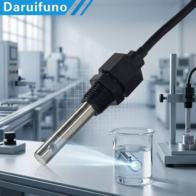
DEC890 Online Conductivity Analyzer RS485 Modbus 5 Point Calibration Pure Water Semiconductor Process
The DEC890 online conductivity analyzer is configured for high-precision, low-range measurement in pure water and process chemistry. It resolves 0.01 uS/cm in the 0~20 uS/cm range and supports up to five calibration points, so the instrument remains traceable across the full span from demineralised water to brine. Isolated power and communication eliminate ground loop noise from VFD driven pumps and high power rectifiers, a frequent cause of unstable readings in semiconductor and metallurgy plants.
Product Overview
This configuration is aimed at technical water systems where conductivity is a critical quality attribute rather than a trend indicator, and where unstable low-range readings translate directly into product loss or compliance exceptions.
Key Advantages
- 0.01 uS/cm resolution in the lowest range makes the analyzer suitable for demineralised water, RO permeate and ultrapure water loops.
- Up to five calibration points (dry air, 84, 146, 1413 and 12880 uS/cm) provide traceable accuracy across a wide dynamic span.
- Offset and factor based two-point calibration gives a fast routine procedure for monthly verification.
- Isolated power supply and communication remove ground loop interference from VFD pumps, rectifiers and welding equipment.
- RS485 Modbus-RTU with documented register map, full register-level control of range, calibration and temperature correction.
- Precision graphite cell with replaceable measuring head keeps drift low and long-term cost of ownership predictable.
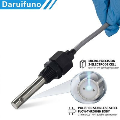
- Stainless steel 316 and POM IP68 construction supports sanitary, flow-through and inline installation in technical water systems.
Technical Specifications
| Measuring principle | Graphite two-electrode measurement principle |
|---|
| Measuring range | 0~20 µS/cm, 20~200 µS/cm, 200~2000 µS/cm, 2~10 mS/cm |
|---|
| Resolution | 0.01 µS/cm, 0.1 µS/cm, 1 µS/cm; temperature 0.1 °C |
|---|
| Accuracy | ±1% of the measuring range |
|---|
| Temperature compensation | 0~50 °C, automatic or manual compensation |
|---|
| Calibration method | Offset calibration, factor calibration, multi-point calibration (up to 5 points) |
|---|
| Operating temperature | 0 to 50 °C |
|---|
| Working pressure | 0~1 Bar |
|---|
| Waterproof level | IP68 |
|---|
| Power supply | DC 9~36 V, power consumption about 0.2 W |
|---|
| Electrical isolation | Power supply and communication are isolated |
|---|
| Communication interface | RS485 Modbus-RTU, default address 17, 9600 bps, no parity, 1 stop bit |
|---|
| Housing material | Stainless steel 316 and POM |
|---|
| Dimensions | Diameter 37 mm, total length about 261 mm |
|---|
| Process connection | 1 inch NPT thread at both ends |
|---|
| Cable | Standard 10 m shielded cable, length customizable |
|---|
| Connector | M16 |
|---|
| Lowest measurable range | 0~20 uS/cm with 0.01 uS/cm resolution |
|---|
| Calibration points supported | Up to 5 points |
|---|
Applications
- Demineralised water, RO permeate and ultrapure water production lines
- Semiconductor and electronics rinse water and chemical dilution control
- Boiler make-up water, condensate and cooling water quality monitoring
- Pharmaceutical and food grade water systems
- Laboratory and pilot plant conductivity measurement
- Electroplating, anodising and printed circuit board process baths
Installation and Maintenance Notes
Install the sensor at a stable, low-turbulence point of the pipeline where bubbles are not easily generated, or install it submerged with the measuring front end facing the water flow and deep into the moving water body. Keep the graphite electrode surface clean and never touch or wipe it with hard objects or oily materials, otherwise the reading will drift and recalibration will be required. The measuring unit is a replaceable structure, so the running cost of long-term monitoring stays low. Routine visual inspection and calibration verification are recommended monthly, and the seal should be serviced every two years.
FAQ
Q1. What resolution can the analyzer provide?
A: 0.01 uS/cm in the 0~20 uS/cm range, 0.1 uS/cm in the 20~200 uS/cm range and 1 uS/cm in higher ranges, with 0.1 C temperature resolution.
Q2. Why does a low-range measurement need multi-point calibration?
A: A single factor cannot describe the whole span. The analyzer stores calibration points at dry air, 84, 146, 1413 and 12880 uS/cm so accuracy is maintained in both pure water and concentrated solutions.
Q3. How is the reading transferred to my control system?
A: Through RS485 Modbus-RTU. The measurement is a 4-byte floating point value in little endian byte-swapped order, and the register map is documented in the manual appendix.
Q4. Does the analyzer need a separate temperature sensor?
A: No. Temperature is measured inside the cell and compensation from 0 to 50 C can run automatically or manually, and the temperature deviation can be corrected by register.
Q5. Is the unit affected by VFD or rectifier noise?
A: Power supply and communication are electrically isolated, which removes the ground loop noise that usually causes unstable low-range readings.
Q6. Can I reset calibration to factory state?
A: Yes. Writing value 33 to register 33 with function code 06 restores the factory calibration parameters.
Ordering and Packaging
Each sensor is packed in a shock-proof foam insert with a corrugated export carton. The standard supply includes the sensor, 10 m cable and a user manual. Cable length, connector type, thread specification and private-label packaging can be customized; please confirm your range, mounting method and communication protocol when placing an order. Our engineers support commissioning, Modbus register mapping and calibration training.
Send your measurement range, medium and mounting method, and we will reply with a matching configuration and quotation within one working day.


 Your message must be between 20-3,000 characters!
 English